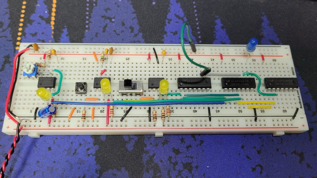
A clock is the most basic but one of the most important components of a CPU. Every aspect of the CPU will perform an action based on a clock cycle. The clock generates a pulse every period, forming a square wave pattern.
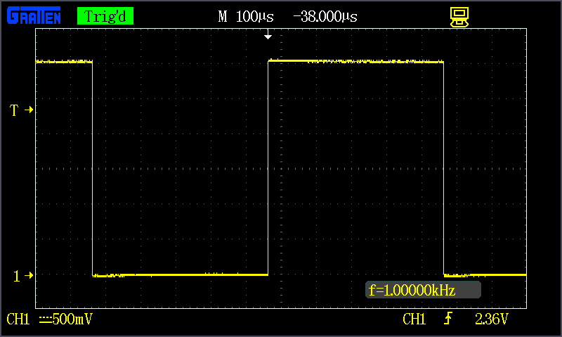
The 555 Timer IC chip is designed to fulfill this purpose. Released in 1972, it is still widely used in many applications. The basic mechanism for measuring time is done by resistors and a capacitor. The clock speed can be adjusted by changing the resistors and capacitor, which affects the time it takes for the capacitor to charge and drain.
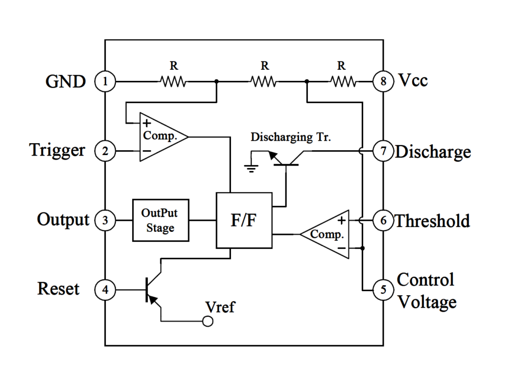
In this project two 555 chips are used for different modes.
Astable clock
An astable, “not-stable” in other words, means the clock does not have a stable state to fall to. This means the clock will switch between high and low and will keep running without human intervention.
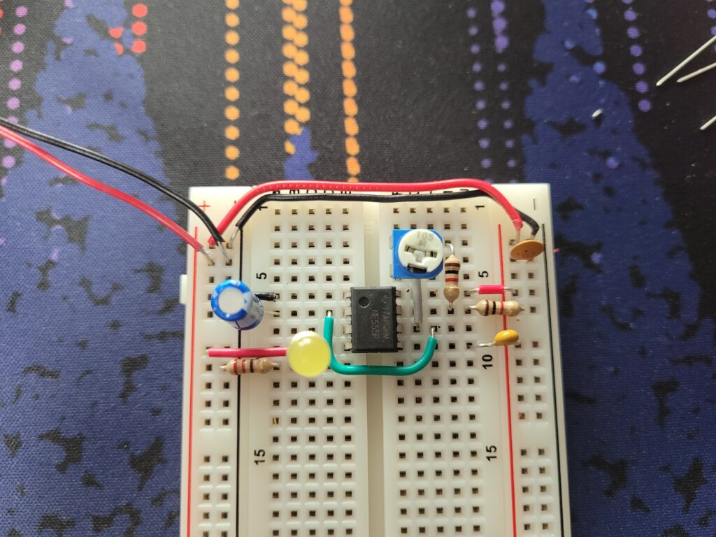
Pin 1 is ground, and Pin 2 is grounded via 1uF capacitor while also leading to Pin 6 for the astable mode. An LED is connected to Pin 3 to show the output (the clock pulses), and Pin 4 is tied to high to prevent resets.
Pin 5 can be left empty, but a 0.01uF capacitor was added as per the manufacturer’s recommendations. On Pin 7, the discharge pin, two 1K Ohm and one variable resistor was added. The variable resistor can go from 0 to 1M Ohm, so current is forced to go through at least one 1K Ohm resistor to prevent shorting (when the variable resistor is at 0 Ohms).
From the datasheet, the period of the pulse can be calculated from:

RA is the first 1K Ohm resistor bridging the 5V line and Pin 7. RB is the variable resistor, and C1 is the 1uF capacitor leading from Pin 6 to ground.
RB has a range of 1K Ohms to 1M Ohms (precisely 1.001M Ohms) – which leads to f having a value between 1.43Hz and 720Hz. About 7 million times slower if we compare by pure clock speeds to modern desktop processors, not even accounting for other factors.
Providing power to this assembled clock, turning the resistor clockwise increases the resistivity, making the clock run slower. Turning it counterclockwise makes the LED blink faster until it is indistinguishable by eye.
Monostable clock
A monostable clock has only one stable state, either high or low. This means the clock will return to its stable state even we force a state change. In this case the monostable clock will be set to low by default, and pressing a button will emit a single clock pulse. This will allow the user to control the progression of CPU instructions manually, which will be very handy in debugging the system later.
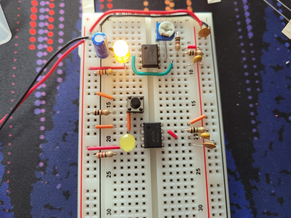
This is very similar to the setup of the astable clock. Pressing the button will charge the capacitor, and a 1M Ohm resistor will drain it. The reason a 555 chip was used instead of just using the button itself to create a signal was to debounce the signal. The physical construction of the button makes a “bouncy” signal, when the contacts in the button bounce around and contact a few times more than intended.
Bistable clock
A bistable clock has two stable states, meaning it is fine with being either high or low. This may sound like a regular switch. However, the same bouncing problem plagues the switch as well, meaning it cannot be used by itself.
The SR latch embedded within the 555 timer can be used to debounce the switch.

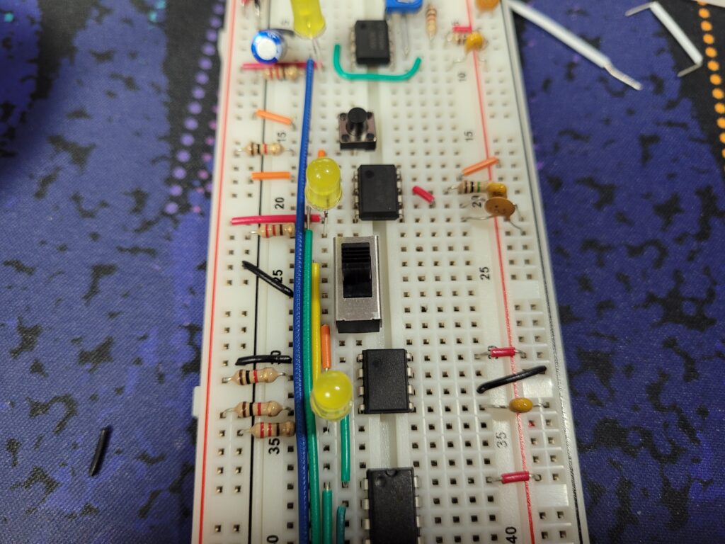
The basic construction is the same as the first two clocks.
Combination logic
The user will need to be able to easily switch modes. The bistable clock can be used to select either mode. Some simple logic gates can be used to combine the clocks into one, and only output the pulse of the selected clock.
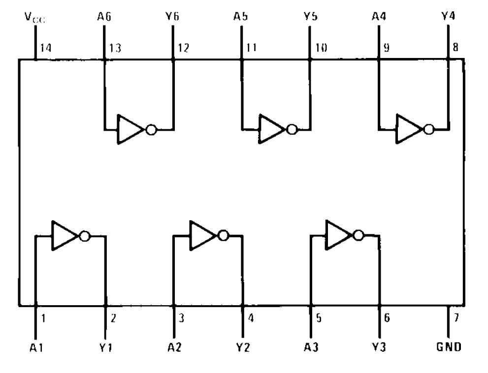
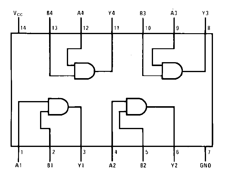
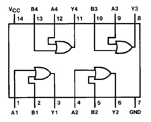
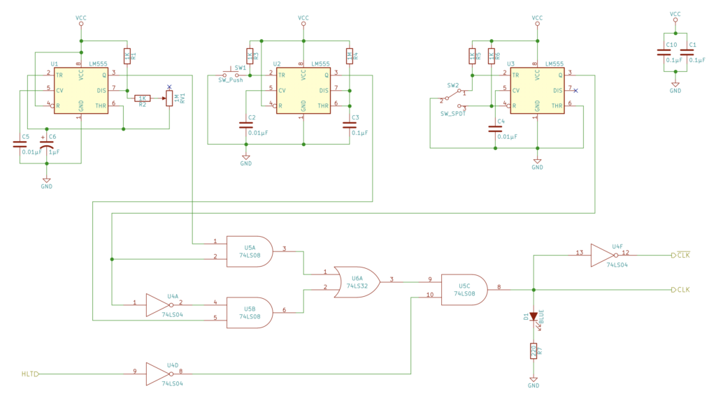
The selector signal goes into two AND gates along with each clock. The OR gate combines the two signals, and finally another AND gate is added for the halt signal. The final clock output is shown via LED.

The green jumper wire is where the halt signal comes in, but for now it is set to the 5V line.
