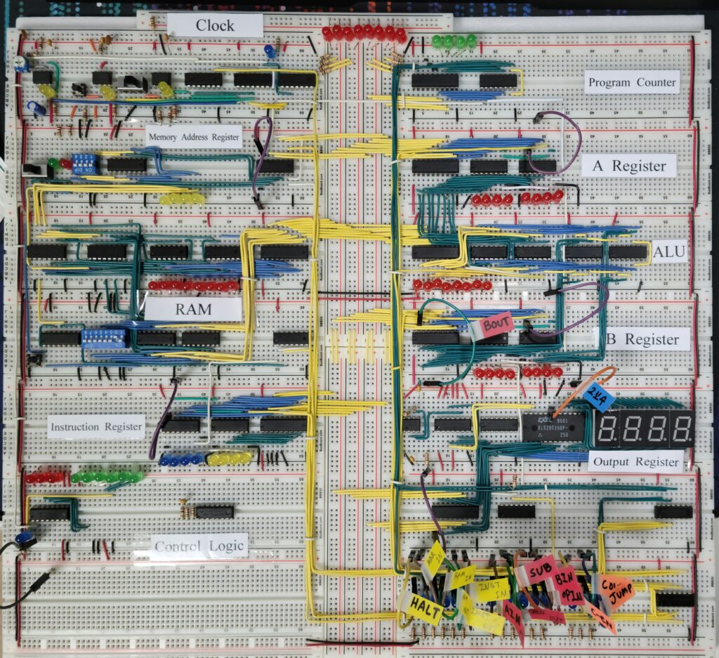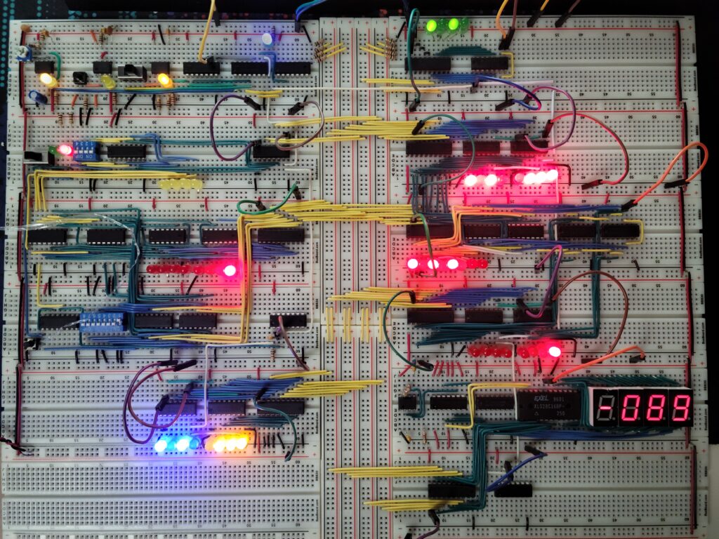
Finally time to bring all the parts together and tie them to the bus.
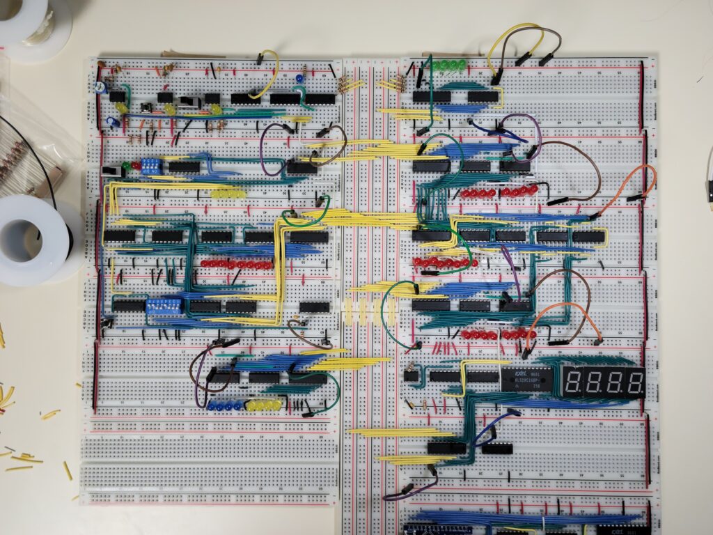
Starting from the top, left to right:
Clock, Program Counter, Address Register, Register A, RAM, ALU, Instruction Register, Register B, Control Logic, and finally Display / Output Register.

This is a test run of the CPU. It’s a counting program, where Register A is set to zero, Register B is set to one, and the ALU is set to add the two values. Technically this is not a program since the program counter nor the RAM was read to decode instructions. Nonetheless it is a nice demonstration.
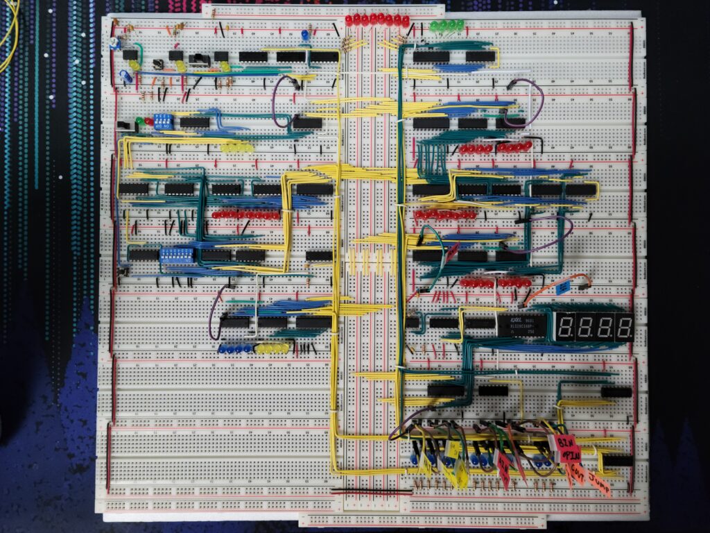
Bringing all the control lines down to the bottom right, and labeling the jumper wires. This provides a convenient place to manually toggle things like ALU input toggle, two’s complement display mode etc.
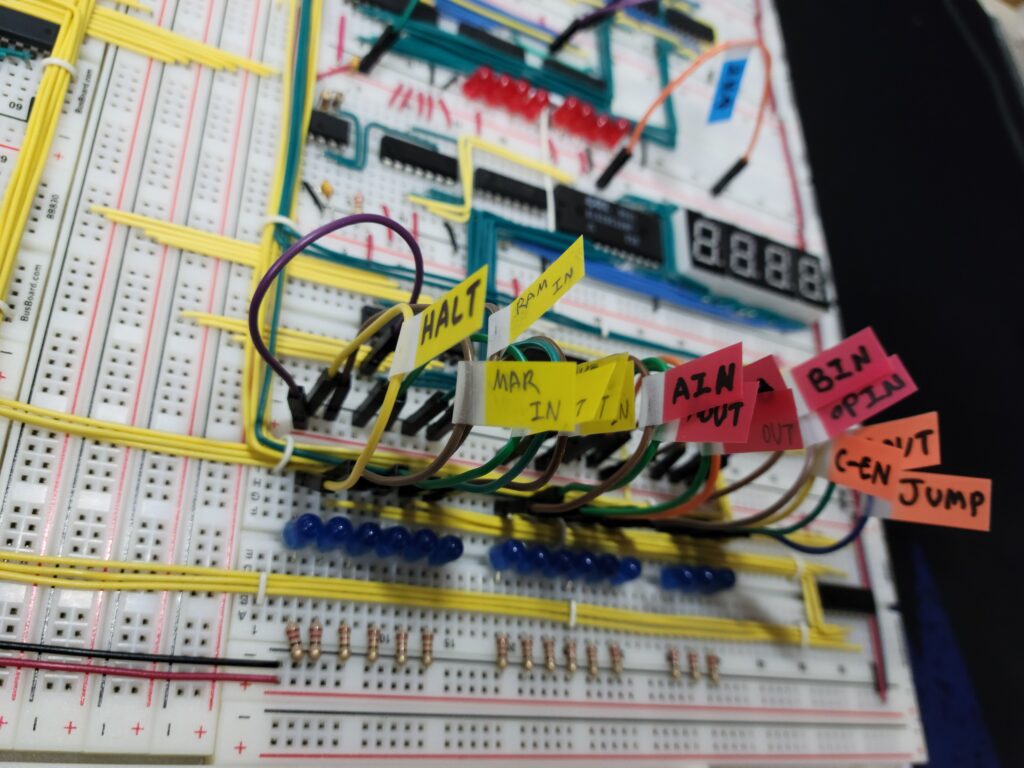
And labeling each part of the CPU.
