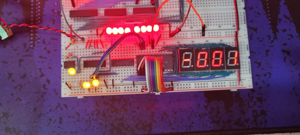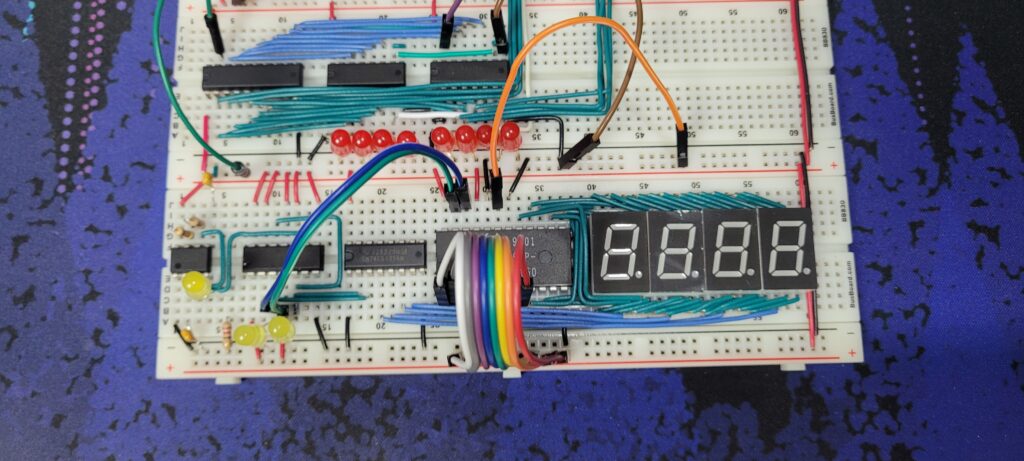
The output of a CPU will be shown as a decimal number, which means for this 8-bit CPU the ranges will be -128~127 (signed) or 0~255 (unsigned). Therefore four 7-segment displays (three for each digit, one for the minus sign) are needed. On the surface, highly complicated logic and wiring seems to be necessary to run all four displays – four displays, seven pins each equals 28 pins to control.
Fortunately, the human eye can’t tell the difference of four displays turned on all at once, or one display at a time blinking once rapidly. Furthermore, the signal decoding can be done by mapping all signals to the corresponding 7-segment pattern. Ben Eater’s video does a fantastic job of using a ROM to store the display information to the binary value.

Using this, a display can be built. The leftmost chip is the 555 timer, which pulses rapidly. The chip next to it is a 74LS107 Dual J-K flip flop. This is currently used as a 2 bit counter. The third chip is a 74LS139 2-4 Decoder which decodes the counter’s value. This chip pulls the corresponding line of 0~3 to low. This output is tied to the ground pins of each display, meaning the counter and the decoder will only allow one out of four displays to glow at a time. This means that all the same segments of the displays can be tied to one line, and into the ROM.

