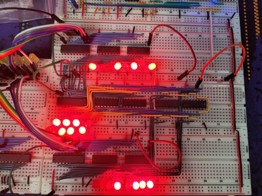
The Arithmetic & Logic Unit is the part of the CPU that actually handles calculations. Their most basic functionality is addition, which are done by (aptly named) adders. Each adder handles addition of each digit.
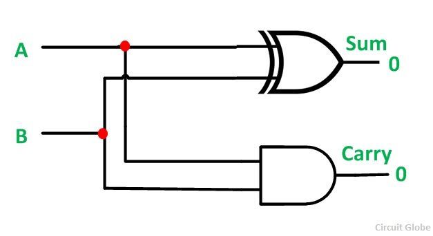
The most simple form of adder is created by combining one XOR gate and one AND gate. If either input is one, the sum is one. If both inputs are one, the sum is zero, but the carry bit is set.
Technically it is possible to chain eight of these simple adders together to form an 8-bit adder. However, this will significally increase the complexity and size of the breadboard computer. Fortunately, a single chip that packages all of this together exists.

The 74LS283 is a 4-bit ALU, so an 8-bit ALU can be obtained by chaining two together, the carry bit (C0 pin) going into the first input (C4 pin) of the second ALU. If a carry happens on the final eigth bit, no further operations will be executed to handle this result. It will only be used as a carry flag for the CPU to use.
Subtraction by Addition
Adders are called adders for a reason. They can only add. However, using two’s complement it is possible to perform subtractions. To get a two’s complement number from a regular binary number, the common procedure is to reverse the bits (0 to 1, 1 to 0) of each digit and finally add one.
In hardware terms, this means a two’s complement number is obtainable by running each digit through an XOR gate, then adding one at the ALU’s input.
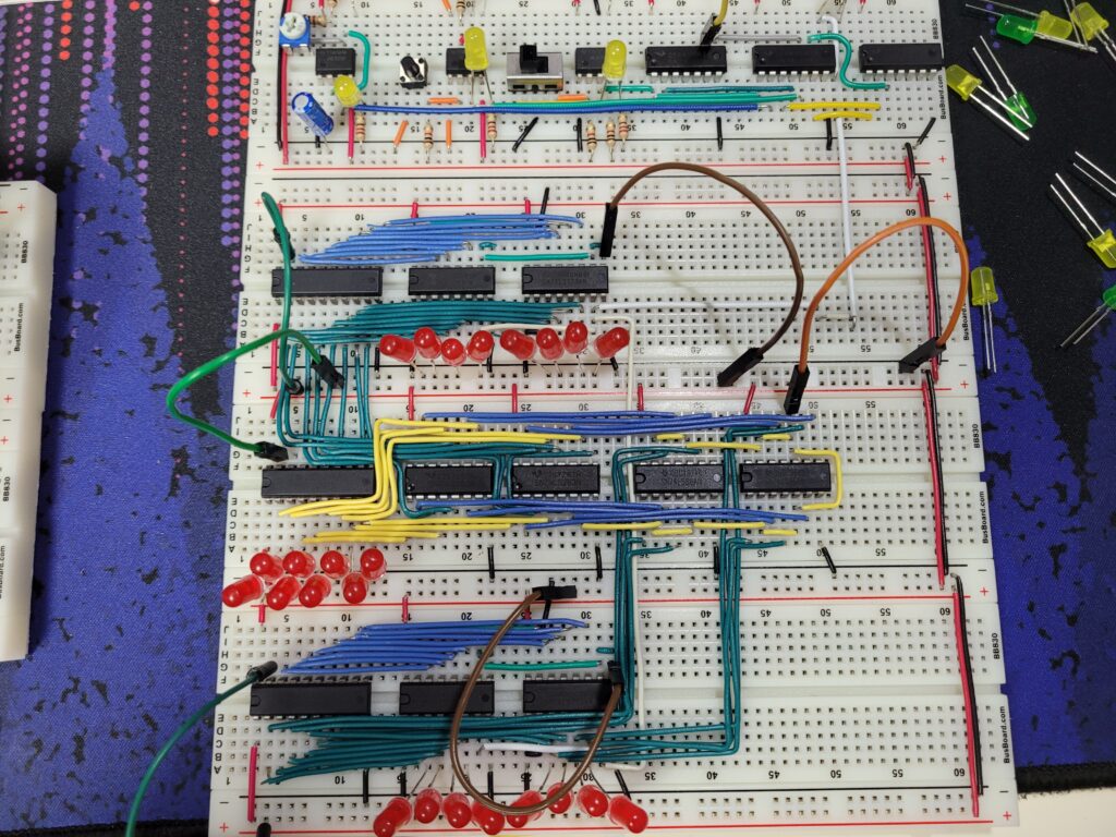
The current stack of breadboards have now expanded to: Clock, Register A, ALU, and Register B.
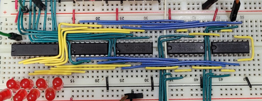
The 74LS86 Quad XOR provides four XOR gates per chip, so the first part of getting the two’s complement number is achieved by using two of them. The yellow wire surrounding the XOR gates tie all of the first inputs together, and are finally chosen between power and ground with the orange jumper wire. Giving power to these will make the gates flip all bits. The one piece of yellow wire bridging the ALU and the XOR gates act as an input to the first bit of the ALU – the “add one” part of deriving the two’s complement.
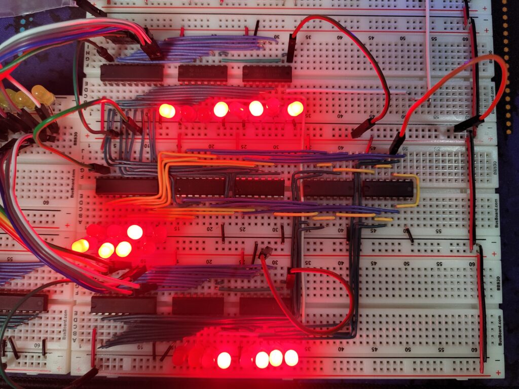
Testing the ALU, Register A has 1001 0101 (149) and Register B has 0001 0111 (23). The output from the ALU is hard to see since the LEDs are not in a straight line, but it has correctly added the two numbers together, resulting in 1010 1100 (172).

Doing the subtraction test, the orange jumper cable is plugged into power to switch to two’s complement mode. Now the ALU outputs 0111 1110 (126), which is also correct.
